When a wire fails in the Power Wheels or you apply speed modifications, you must know each wire. The power Wheels wiring diagram helps you to understand each wire and its operation.
The power Wheels Wiring diagram includes batteries, motors, switches, throttle, relays, and all the wires of Power Wheels. Some models may have a controller/ESC/Switch, which is also included in the wiring diagram. To understand the Power Wheels wiring diagram, first, you must understand the series and parallel wiring.
Table of Contents
Important Factors About Power Wheels Wiring Diagram.
- Every model of the Power Wheels may have a different wiring diagram based on the parts involved in the diagram.
- Some diagrams may include a single, and some may include two motors.
- The batteries decide the voltage of Power Wheels; multiple batteries connection is also shown in the wiring diagram. It is very necessary to understand the parallel and series battery wirings.
- Some Power Wheels may have a controller, which should also be shown in the wiring diagram.
- You should focus on the voltage compatibility of the motor and battery when creating a Power Wheels wiring diagram.
Understanding the Parallel and Series Wiring.
Parallel Wiring
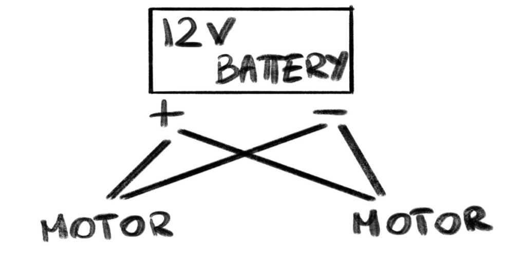
Suppose your power wheels have one 12V battery and two 12V motors. Now to run the motors, you have to give full 12V Power to the motors. The parallel wiring can give full 12V to both motors.
Parallel wiring is simple; you will connect the positive side of the battery to the positive sides of motors with two different wires, similarly connect the negative side of the battery to the negative sides of motors with two wires. Look at the diagram for parallel wiring.
Series Wiring
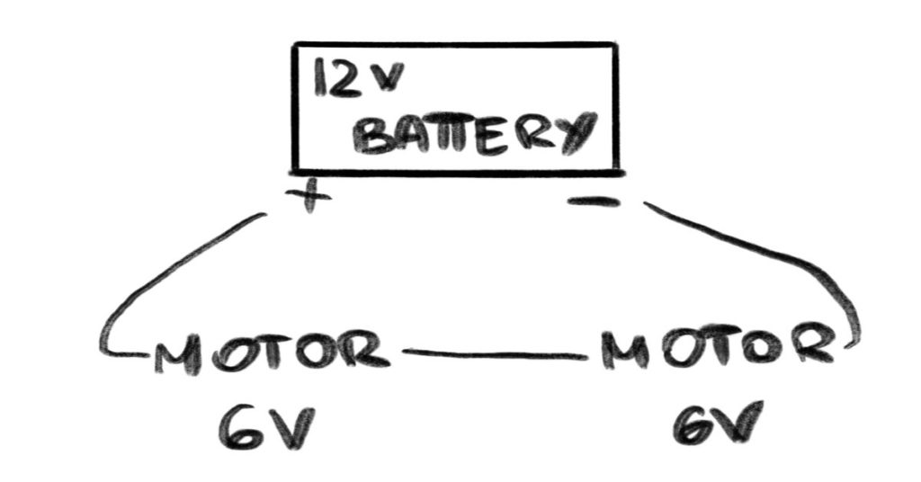
Series wiring is used to divide the voltage of the battery in the Power Wheels. If you have one 12V battery and two 6V motors you can connect the motors to batteries in series. The battery voltage will be divided into 6 6 volts.
In series wiring, the battery’s positive side is connected to the positive side on one motor, and then from that motor, the same wires go to the positive side of the second motor; only one wire is used in this connection.
Similarly, the negative side of the battery is connected to both motors with one wire. Have a look at the diagram.
Let’s see how different power wheels wiring works.
Power Wheels Wiring Diagrams With Single Battery, Parallel.
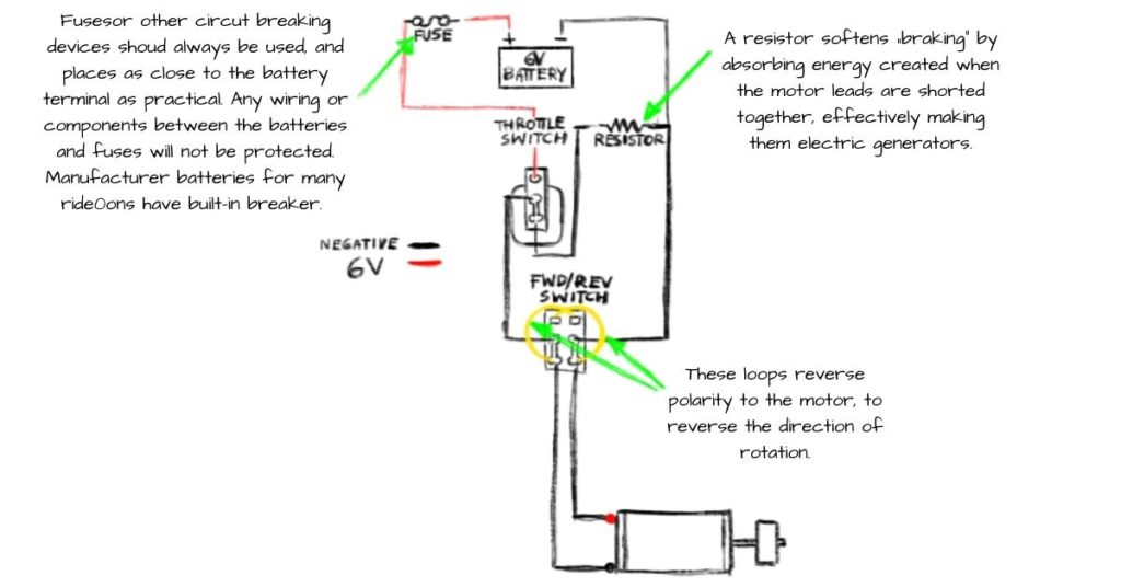
Let’s take 6V Power Wheels as an example, and the same rules will be applied on 12V or 24V Power Wheels. A basic 6V Power Wheels consist of one 6V battery, one 6V motor, a throttle switch, a Forward/Reverse switch, a fuse, and a resistor.
In 6V Power Wheels, the positive side of the battery is connected to the first pin of the throttle switch.
The throttle is usually a three-pin switch, this connection is made through a fuse, which is used to break the circuit, and it is the best practice to put the fuse near the battery; many power wheels batteries have breakers installed in them.
The forward/reverse switch is a six-pin switch. Now the middle pin of the throttle switch goes into the left middle pin of the F/R switch.
Now the negative side of the battery is connected through a resistor to the last pin of the throttle switch; the resistor softens the current flow while you press the brake.
The negative side of the battery is connected to the right middle pin of the F/R switch.
The first two pins of the F/R switch are connected to the last pins; the upper right one is connected to the down left one, and the upper left one is connected to the downright one; these loops are done to reverse the polarity.
The left end-pin on the F/R switch is connected to the motor’s negative side, and the right end-pin of the F/R switch is connected to the positive side of the motor.
With this diagram, 6V Power Wheels can work normally. It is a parallel wiring diagram, and you can follow the same diagram for 12V or 24V if your Power Wheels have one battery and one motor. The Diagram is given below.
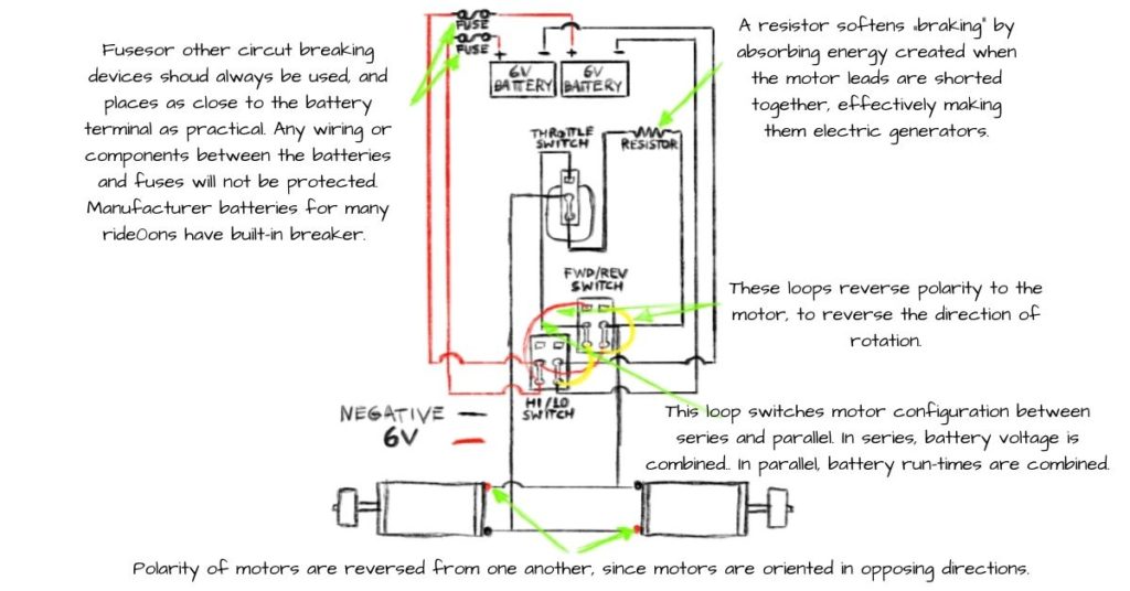
Power Wheels Wiring Diagrams With Single Battery, Series
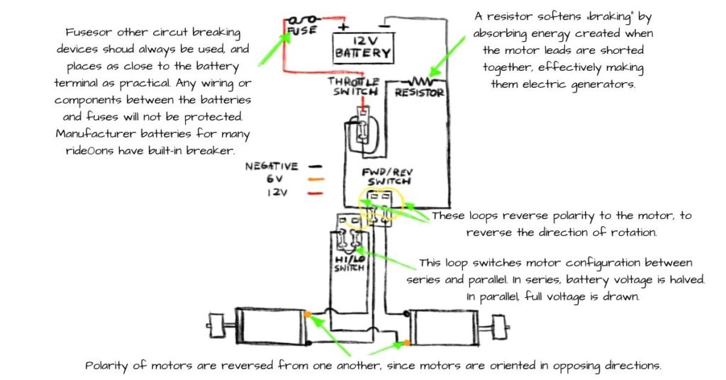
Now for the double motor, the diagram is mostly similar. The Power Wheels with two motors consists of a High/Low switch which is generally the controller or ESC.
The battery, throttle, and F/R switch connections are the same as above.
The left end-pin of the F/R switch is connected to the negative side of the left motor, and the right end-pin is connected to the negative side of the right motor; this is a loop.
The High/Low Switch is also a six-pin switch used to switch the motor between series and parallel.
The F/R switch is also connected to the High/Low switch; down left and down right of the F/R switch are connected to the up left and up-right of the High/Low Switch, respectively.
The left middle pin is connected to the positive side of the right motor, and the right middle pin is connected to the positive side of the left motor.
The upper pins are left open the same as the F/R switch. The High/Low switch pins at the down are connected to each other in a series.
As mentioned above, this will switch the motor between series and parallel. The diagram below shows the system of how a 12V battery can run two 12V motors.
Power Wheels Wiring Diagram With Multiple Batteries, Parallel/Series.
You can connect the multiple batteries in parallel to make it one battery with the same voltage. For example, you have one 6V motor and two 6V batteries. You can connect the batteries in parallel, then it will generate 6V, and you can run the 6V motor easily.
What if you have two batteries and two motors? Again, we will consider both parallel and series battery connections. Let’s see how two combined 6V batteries can run two 6V motors. The battery connection will be parallel for this.
This system involves two 6V batteries, two 6V, throttle switch, F/R switch, High/Low switch resistor, and fuses. The switches are similar as described in the previous one.
- First of all, the battery connection will be parallel, connecting two different wires into the positive sides of the battery.
- The positive side of the left battery goes to the left down pin of the High/Low switch, and the positive side of the right battery goes to the left middle pin on the High/Low switch.
- The negative sides are connected in a mirror position, the left battery negative side to the right middle pin of the High/Low switch, and the right battery to the down-right pin of the same switch.
- Now High/Low switch and F/R switch are connected through positive and negative wires.
- In the positive connection, the down-left pin of the High/Low switch is connected to the up left of the F/R switch, and the middle left of the High/Low switch is connected to the down-right pin of the FR switch.
- And in the negative connection, the down-left pin of the F/R switch is connected to the down-right pin of the High/Low switch. Also, the same down-left pin of the F/R switch is connected to its upright pin. It is done to create the loop to reverse the polarity in the motor.
- The throttle switch is connected to the F/R switch and both motors. The upper pin on the throttle switch is connected to the middle left pin of the F/R switch.
- The middle pin of the throttle switch is connected to the negative side of the left motor and the positive side of the right motor; the middle pin is connected to both motors.
- The down pin of the throttle is first connected through a resistor to the middle pin of the F/R switch, then it is connected to both motors, to the positive side of the left motor, and the negative side of the right motor. Have a look at the diagram to understand this whole scenario.
This diagram works in both parallel and series, and you can run two 6V or 12V motors on two 6V batteries. The other way to do that is to install relays.
Power Wheels Wiring Diagram With Multiple Batteries, Relay.
Now you understand the connections and how they are done. Now let’s see how multiple batteries are installed in series with relays and two motors. The relays are used to switch the motor configurations between series and parallel; relays are considered safer than complicated wiring connections.
Let us consider the same scenario of the previous Power Wheels Wiring Diagram With Multiple Batteries and add two relays. I do not have to describe the connections now; you can make connections as described in the diagram.
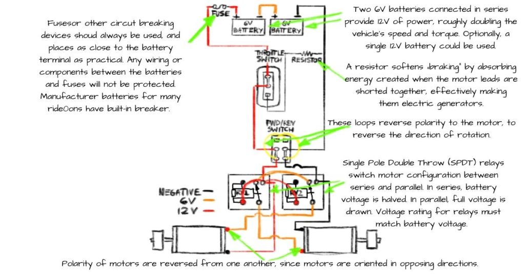
This diagram involves two types of positive wires. One is 6V and the other 12V. all these double battery diagrams are based on two same voltage batteries. What if the two battery voltages are different.
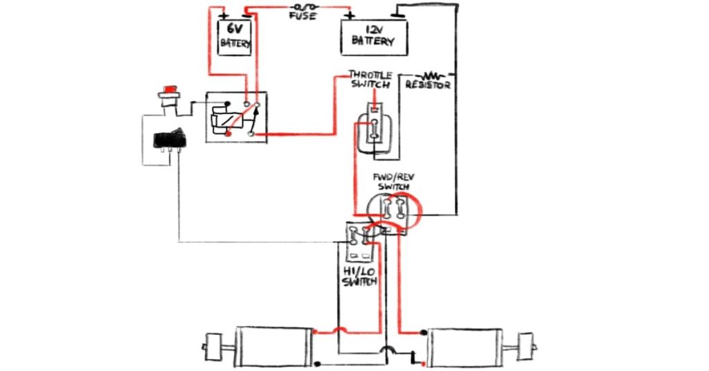
Power Wheels Wiring Diagram With Multiple Batteries With Different Voltages, Relay.
Batteries can have different voltages; for example, you are using one 12v battery and one 6v battery. You can connect them in series with a relay installed between the power switch and the 6v battery. The 6v battery will be on the positive side, and the 12V battery will be on the negative side.
The diagram below shows the system based on 12v and 6v batteries. The relay will balance the current flow in the system. You can make all the connections similar to the diagram below.
Conclusion
Power Wheels Wiring diagram helps you repair a failed wire, connect a new electronic part or modify or upgrade the Power Wheels. When you have a wiring diagram, you can easily check the wires with a voltmeter when a problem occurs.
The wiring diagram shows whether the connection is parallel or series. The parallel connection is used for the same voltage, and the series connection is used for halving or adding the voltage. You easily connect single to single, single to multiple, and multiple to multiple connections in terms of batteries and motors.


